Development Division
Large Power Products Management Division
Power Solution Business
YANMAR Technical Review
Two-stage Turbocharging for Four-Stroke Medium-Speed Diesel Engines
Abstract
Two-stage turbocharging has the potential to improve engine efficiency through its use in conjunction with an advanced Miller cycle to overcome the trade-off between fuel consumption and NOX emissions. Yanmar has released the 6EY26W, a marine propulsion engine that uses the two-stage turbocharging system to improve specific fuel oil consumption (SFOC) by 8g/kWh while also satisfying the IMO NOX Tier 2 regulations. This article describes this new development in turbocharging for four-stroke medium-speed diesel engines and how it can be used to comply with IMO NOX Tier 3 regulations.
1.Introduction
Marine diesel engines have long been subject to a variety of requirements that include better fuel economy, higher output, ability to use heavy fuel oil, and lower noise. In the case of fuel economy, a critical aspect of product quality, Yanmar reduced the fuel consumption of its four-stroke medium-speed diesel engines by 50g/kWh or more between 1960 and 2016. Major factors in reduced fuel consumption have included increasing the maximum firing pressure (Pmax) and improving the gas exchange work, and these are the results of turbocharging technology.

For the turbocharger itself, higher pressure ratio and efficiency, and lower inertia of rotors are continuously requested. The overall system include use of pulse turbocharging, constant pressure turbocharging and twin turbocharging (in which two identical turbochargers are used in parallel) (see Fig. 1), and these are selected depending on the application. Examples at Yanmar include aiming to reduce the fuel consumption of auxiliary engines without compromising load pick up by developing a new mono-pipe pulse system (MPS) of quasi-constant-pressure turbocharging, and improving acceleration performance by using twin turbocharging for propulsion engines.
Recent years have seen greater use of higher pressure turbocharging in response to the tightening of environmental regulations, including the introduction by the International Maritime Organization (IMO) of progressively tighter restrictions on NOX emissions. Earlier-closing Miller cycles1) are one such technique for achieving low NOX that take advantage of this trend and they have been widely adopted to comply with the IMO NOX Tier 2 regulations that require a 20% reduction in NOX relative to Tier 1. Generally, there is a trade off between NOX and fuel consumption whereby reducing NOX increases fuel consumption. Accordingly, finding ways to overcome this trade-off is an important consideration in the development of techniques for reducing NOX, and the combination of the earlier-closing Miller cycle with high pressure ratio turbochargers is one way in which this is achieved. Further approach to increasing the potential for reducing NOX and fuel consumption and providing greater flexibility of engine performance matching is to increase the degree of turbocharging. A technique that has attracted attention in this regard is two-stage turbocharging whereby two different types of turbocharger are used in series2), 3), with pressure ratios from 6 up to a maximum of 12 having been reported by turbocharger manufacturers.
This article describes the latest trends in turbocharging technology of four-stroke medium-speed diesel engines and Yanmar’s two-stage turbocharging system, and presents examples of compliance with IMO NOX Tier 3 regulations.
2.Two-Stage Turbocharging System
2.1.Concept
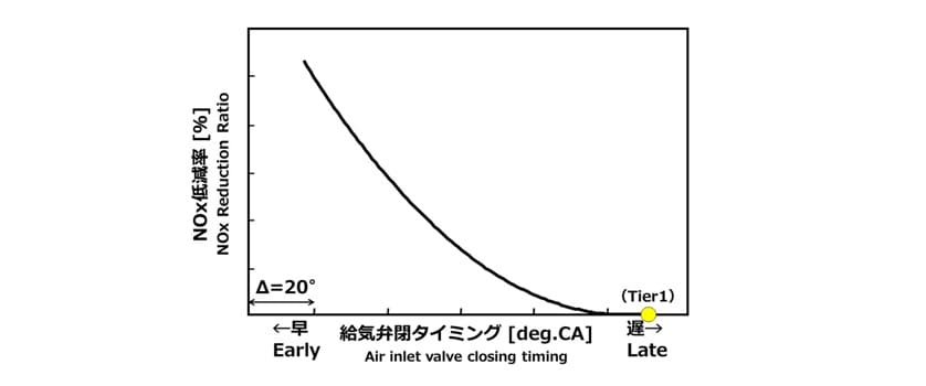
Fig. 2 shows the relationship between the air inlet valve closing timing (IVC) and NOX reduction ratio. The earlier (more advanced) the IVC is, the greater the NOX reduction ratio relative to the Tier 1 standard is. Because the air intake process in the earlier-closing Miller cycle closes the air inlet valve before the piston reaches bottom dead center, the subsequent downward movement of the piston causes the air filled inside the cylinder to expand and its temperature to fall. This results in a lower temperature at the end of compression (air temperature in the cylinder prior to combustion), and a lower combustion temperature, thereby reducing the amount of NOX1).

On the other hand, there are cases in which the lower pressure inside a cylinder resulting from early closing of the air inlet valve degrades fuel consumption. Solving this problem requires that the pressure ratio of the turbocharger be increased so as to supply a greater quantity of air in a short time. This is described in Fig. 3 (the relationship between the IVC and the turbocharger pressure ratio on the condition that constant Pmax is maintained).

The following describes the various types of earlier-closing Miller cycle with reference to the diagram of air inlet valve open and close operation shown in Fig. 4. While different companies use different terminology2), 3), Miller cycle of which inlet valve is closed earlier progressively from the IVC timing near the bottom dead center (“Tier 2” in the Fig.4) are called “strong Miller” and “extreme Miller” respectively. For the Tier 2 specification engine, which aim is to reduce NOX by 20% relative to Tier 1 specification, single-stage turbocharging (a single turbocharger) is used to achieve the higher pressure ratio. The pressure ratio for Tier 2 specification is as high as 5.5 in some cases, if overload is included, and while it depends on the turbocharger manufacturer settings, this is the limit of what is possible with single-stage turbocharging. Accordingly, if a strong Miller or extreme Miller timing is used to reduce NOX by 30 or 40% relative to Tier 1, two-stage turbocharging (dual turbochargers) is needed because the pressure ratios of 6 or higher is required. The terminology used by Yanmar for this is “two-stage turbocharging system”.

Fig. 5 shows the trade-off between NOX and SFOC, and the concepts of two-stage turbocharging system are described by sequential numbers. By combining two-stage turbocharging with a strong Miller or extreme Miller timing, NOX can be reduced to an extent without degrading fuel consumption (①), and by advancing the fuel injection timing within the Tier 2 standards of NOX (②), very low fuel consumption can be achieved (③). This is an advanced version of the technique used to satisfy Tier 2. It can be also expected as a technique for achieving the reduction in energy efficiency design index (EEDI) stipulated by the IMO.

2.2.Application to Marine Propulsion Engines
A two-stage turbocharging system was applied to the Yanmar 6EY26W propulsion engine4) (see Fig. 6). Fig. 7 shows the layout of two turbochargers and two air coolers (A/Cs) located at the end of the engine.
In the two-stage turbocharging system, each of the pressure ratio of the low pressure stage turbocharger (L.P.-T/C) and high pressure stage turbocharger (H.P.-T/C) is lower than that of the single-stage turbocharger and the temperature increase due to the turbocharger is lower as well. Therefore each of A/C capacities for two-stage turbocharging does not need to be as large as an A/C capacity for single-stage turbocharging. This is one of the advantages of two-stage turbocharging, and means total turbocharger efficiency is greater than that for single-stage turbocharging, in particular, which has the same pressure ratio. Because the increase in the temperature of the intake air spoils the reduction in NOX due to the stronger Miller timing, as explained below, it is hard to realize the two stage-turbocharging without the A/C.


2.3.Engine Performance
(1) Computational Performance Simulation
Fig. 8 shows one of the single-dimensional performance simulation models prepared for this purpose. Fig. 9a shows the calculated air temperature at the end of compression at rated load and Fig. 9b the calculated result of overall air-fuel ratio at 25% load. Fig. 9a is part of the evidence for Fig. 2 whereby the earlier the IVC, the lower the temperature at the end of compression. Along with the A/C suppressing the increase in inlet air temperature despite the high level of boost pressure, another likely reason is the higher proportion of adiabatic expansion due to the stronger Miller timing. The vertical axis in Fig. 9b shows the air-fuel ratio relative to a Tier 2 engine (“0” deg CA and single-stage turbocharging) for different IVC timings (with two-stage turbocharging) indicated by the horizontal axis. The purpose of the simulation was to determine the Miller timings needed to restore the air quantity at low speed by applying two-stage turbocharging. In the case of a propulsion engine, the requirements for any technique for achieving low fuel consumption include maintaining smoke and acceleration performance at low speed.


(2) Results of actual engine tests
The actual engine demonstrates that the two-stage turbocharging increases the overall pressure ratio of slightly more than one comparing to that of the Tier 2 compliant engine at the same flow rate. It is the pressure that the single-stage turbocharging cannot achieve and it makes the strong Miller cycle possible.
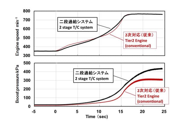
Fig. 10 shows the trade-off between NOX and fuel consumption. NOX is expressed by E3 mode and fuel consumption is for a load of 75%, which is a realistic load and one that is covered by propulsion engine EEDI requirements. Points enclosed in dotted lines on the figure indicate the same fuel injection timing. The application of a two-stage turbocharging system achieves a significant reduction in fuel consumption (③). Fig. 11 shows the results of acceleration performance test. By adopting pulse turbocharging and the H.P.-T/C with low inertia moment rotor, the two-stage turbocharging system demonstrates superior performance of boost pressure pick up and equivalent acceleration time (time to accelerate to rated speed from a low initial speed) despite its using a strong Miller timing4).
The improvement result in the fuel consumption with the combination of an extreme Miller timing and MPS turbocharging is shown by ④ in Fig. 10. Further improvement in NOX and exhaust work leads reduction of 10kg/kWh or more in fuel consumption relative to the Tier 2 engine. However, because testing also found performance degradation at very low load, the incorporation of a variable valve timing mechanism needs to be considered if using an extreme Miller timing.


2.4. Commercialization
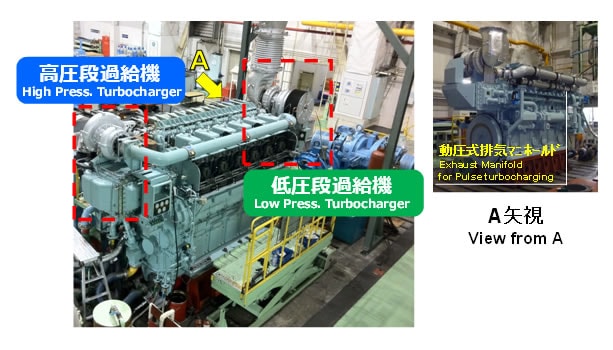
Fig. 12 compares the two-stage turbocharging system layouts on the test engine (left) and a commercial engine used as a propulsion engine for a domestic vessel (right). Fig. 13 shows photographs of the commercial engine, and the right photograph shows a view of exhaust manifold side. On commercial engines, the L.P.-T/C and H.P.-T/C together with their A/Cs have been arranged at both ends of the engine for reasons related to the total engine height and easier maintenance. The reduction in fuel consumption on a commercial engine was 8g/kWh.


3.Application to Engines in Compliance with IMO Tier 3 Regulations
3.1. Example of Application
While selective catalytic reduction (SCR) is often applied by Yanmar and others to comply with the IMO NOX Tier 3 Regulations for four-stroke medium-speed diesel engines5), there are some reports6), 7) describing the combination of Miller cycle and two-stage turbocharging with exhaust gas re-circulation (EGR) and electronically controlled fuel injection system (common rail system)6), 7). These describe the use of two-stage turbocharging (increased air supply) to reduce the increase in smoke associated with EGR, and use of a strong Miller timing to reduce Pmax.
While two-stage turbocharging systems are being applied in this way to make up for loss of performance due to Tier 3 compliance measures in the engine, it is also possible to use them in combination with an SCR system. From the point of view of SCR, key questions include how to reduce the cost of the urea-water solution used as the reducing agent and how to maintain the exhaust temperature described in the following section. With respect to Tier 3, which requires a NOX reduction of 80% relative to Tier 1 in emission control areas (ECAs), reducing the level of NOX at engine exit has benefits that include reducing consumption of urea-water solution by lightening load on the SCR. This is an example of a two-stage turbocharging system being applied as a technique to reduce NOX.
3.2. SCR Requirements
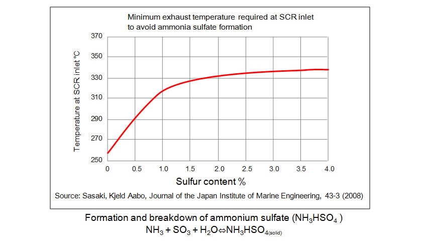
Fig. 14 shows the relationship between the sulfur content of the fuel oil and the minimum exhaust temperature required at the SCR inlet to prevent the formation of acid ammonium sulfate5), 8). When using SCR system, this requirement must be satisfied to maintain the catalyst durability. While the exhaust temperature at engine exit tends to be lower when applying a two-stage turbocharging system, in the case of the test results described in section 2, this is not a problem in practice because of the high engine output and propulsion engine characteristics.
While it is assumed that SCR systems will be installed on engines that have a two-stage turbocharging system to comply with the Tier 2 NOX limit and reduce fuel consumption, Yanmar also intends to look at the balance of pressure ratio between the L.P.-T/C and H.P.-T/C based on objectives such as fuel consumption, reduction in NOX, and engine application, and also integration with other devices.

4.Conclusions
This article has described a two-stage turbocharging system as turbocharging technology for four-stroke medium-speed diesel engines and its application. Note that this system was developed as part of a project for the commercialization of advanced maritime technologies of the Japan Railway Construction, Transport and Technology Agency.
It goes without saying that reducing running costs or reducing fuel consumption is essential to improving life cycle value for customers and maintaining harmony with the global environment. Yanmar hopes that this system, which is only an example, will help the development of the next generation of engines by providing a way to reduce fuel consumption and NOX emissions furthermore.
5.References
- (1)Hamaoka, Journal of the Japan Institute of Marine Engineering, 45-1 (2010-1), 18-21
- (2)T. Behr et al., CIMAC Congress 2013, NO.134
- (3)S. Risse et al., CIMAC Congress 2013, NO.226
- (4)Takahata, Journal of the Japan Institute of Marine Engineering, 50-2 (2015-3),93-97
- (5)Hamaoka, Journal of the Japan Institute of Marine Engineering, 48-6 (2013-11), 30-35
- (6)F. Millo et al., CIMAC Congress 2013, NO.74
- (7)C. Stoeber-Schmidt et al., CIMAC Congress 2013, NO.232
- (8)Sasaki, et al., Journal of the Japan Institute of Marine Engineering, 43-3 (2008), 382
Note: This article is a modified reprint of an article that appeared in the Journal of the Japan Institute of Marine Engineering (51-2).
-IMPORTANT-
The original technical report is written in Japanese.
This document was translated by Research & Development Management Division.
Author
