Engineering & Development Dept.
YANMAR CONSTRUCTION EQUIPMENT CO., LTD.
YANMAR Technical Review
Introduction of Minimal Swing Radius Excavator "B7-6" that has Evolved Comfort and Equips SIGMA Boom.
Abstract
The minimal-swing-radius hydraulic excavator (MSRX), which is sold mainly in the Japanese market, has a boom offset mechanism to both sides.
Featuring easy operation and excellent practicality in the confined space of a construction site, the MSRX is commonly used to lay water supply, sewage and gas piping, and communication cables.
Yanmar released its new B7-6 in 2015. The B7-6 has the same SIGMA boom (offset boom) as previous models, which offers excellent performance for deep digging.
A key design concept for the B7-6 was to provide a larger cabin, a feature requested by many users. This article describes the technology adopted to achieve this objective and the other new features on the B7-6.
1. Introduction
The minimal-swing-radius hydraulic excavator (MSRX), sold mainly in the Japanese market, is characterized by having an implement with a boom that can be offset to either side. It is widely used for tasks such as laying water supply, sewage and gas piping, and communication cables thanks to its ease of use (ability to dig in a straight line when facing forwards, even when performing trench digging on the boom side of the machine (see Fig. 1)), and its practicality on roads or in built-up residential areas (due to the small amount of the upperstructure overhanging from the undercarriage when rotating).
In recognition of the excellent deep digging performance of Yanmar’s proprietary SIGMA boom (Σ boom), the B7 series has been increasing sales ever since the Σ boom was first adopted in 1999. The B7 has been released in 2015 as all new B7-6, and was undertaken to coincide with the introduction of new exhaust emission regulations in Japan (see Fig. 2).
This model change aimed to deliver machines that are easy to use from the customer’s perspective, adopting the highly regarded Σ boom and incorporating a variety of improvements requested for previous models. In particular, with the improvement of operator comfort by providing a larger operator space as a frequent request, the adoption of a large cabin was one of the development concepts.
This article describes the technologies adopted to allow for the large cabin, the new features included in these latest models, and the technologies that made them possible.


2. Technologies Used to Allow for a Large Cabin
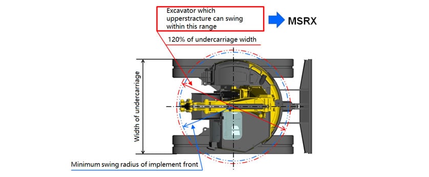
Cabin size has a significant and direct influence on comfort. MSRXs are defined in JIS A8308 as hydraulic excavators that are intended for use in confined spaces and have a rotating upperstructure and an implement (including the minimum swing radius of the front of attachment) which can swing within 120% of the undercarriage width (see Fig. 3). This definition restricts the space that is available for the cabin.

Despite this restriction, the B7-6 has the same large cabin as the ViO80-1A true zero tail swing excavator, with 200 mm more foot space and a width that is 160 mm wider than the previous model (see Fig. 4). This provides a comfortable environment, with 40% more interior space than before.

To provide this large cabin, the boom’s support point was shifted farther toward the right side of the machine and the amount of boom offset was changed (increasing the left-hand offset and decreasing the right-hand offset) to keep the work range equivalent to that of previous models.
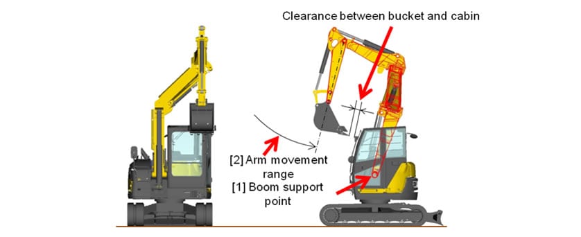
The increased size of the cabin and the greater left-hand offset has the effect of reducing the clearance between bucket and cabin. To keep the clearance between bucket and cabin the same as previous models and to ensure that the minimum swing radius of the implement front (1320 mm) does not exceed 120% of the width of the undercarriage divided by two (1362 mm), the following countermeasures were implemented: [1] The boom’s support point was moved forward and to a higher position, and [2] improvements were made to the operating range of the arm (see Fig. 5).

Because the change in offset results in a higher load on the implement and frame, FEM analysis (see Fig. 6) and bench testing were carried out to check the strength and ensure that Yanmar’s standards are met.

3. Machine Features and Technologies
The following sections describe the new environmental, comfort, safety, maintenability, and crane operation features introduced in the B7-6.
3.1. Environmental Features
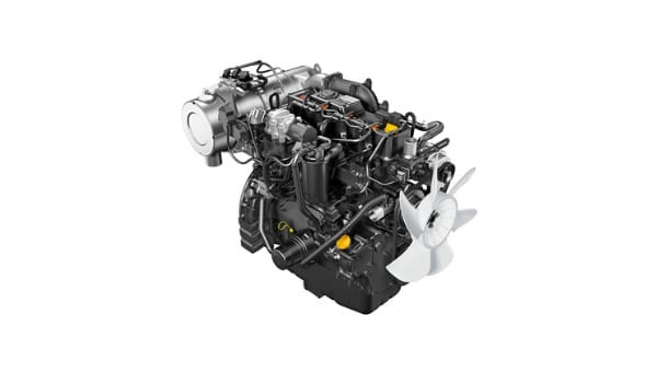
The B7-6 is installed with a clean Yanmar electronically-controlled common-rail engine with a diesel particulate filter (DPF) that satisfies the 2014 exhaust emission regulations for “non-road special motor vehicles” in Japan (see Fig. 7). An engine fitted with a DPF requires regeneration to burn off the soot accumulated in the filter. Yanmar has adopted its own original three-step regeneration control (see Fig. 8) in which the first and second steps do not require to stop in operation because they are performed automatically during normal operation. While the third step is performed manually by stopping operation once a certain amount of soot has been accumulated, the DPF’s high level of regeneration performance can complete it quickly. This reduces unnecessary fuel consumption while also minimizing total emissions of exhaust gases.


Furthermore, the availability of an “eco mode” that reduces the engine speed by 200 min-1 from high idle can reduce fuel consumption by approximately 9%. This mode can be selected with a switch easily. Similarly, further fuel savings are provided by the availability of an “auto deceleration mode” that automatically reduces the engine speed to a low idle if the machine is not operated for four seconds or longer.
3.2. Comfort
The large cabin on the new model is supported by liquid-filled anti-vibration mounts (see Fig. 9) with two levels of hardness that are combined in a way that maximizes vibration damping. This significantly reduces internal cabin noise due to transmitted vibration, providing a quiet environment with a sound pressure level of 73 dB(A). The superior ride comfort resulting from the minimizing of vibration also reduces operator fatigue.

Meanwhile, changes to the air conditioning system and improvements to air flow have significantly improved cooling performance. As this can quickly cool the cabin when the operator gets in during the heat of summer, a comfortable working environment is achieved within a short period of time (see Fig. 10).

3.3. Safety
The cabin features a high degree of safety in compliance with international standards, including the Roll Over Protective Structure (ROPS) standard for ensuring an operator wearing a seatbelt will be kept safe even if the machine overturns and the Falling Object Protective Structure (FOPS) standard for ensuring operator safety in the event an object falls on the cabin.
3.4. Maintenability
SmartAssist, which uses GPS and a communications unit to enable monitoring the machine’s operation status and mechanical condition remotely, is provided as a standard feature on the B7-6. Along with actual maintenance work, this facilitates providing users with maintenance notifications based on machine operating time to reduce lifecycle costs by preventing breakdowns due to lack of maintenance. As details of failures and the location can be immediately determined in the event that a failure does occur on a machine, it also minimizes machine downtime by enabling a quick on-site response, including bringing any required spare parts (see Fig. 11).

3.5. Crane Operability (For Japanese market only)
With the previous model, models with crane specifications accounted for more than 90% of factory-delivered machines. In terms of maximum crane lifting capacity which is an important consideration for customers, the B7-6 has the same 2.5 ton crane lifting capacity as previous models.
As part of the model change, the new crane models also feature a mode for traveling with a suspended load, as specified in the Japan Crane Association (JCA) standard.
While a switch located below the LCD monitor is provided for easy switching between "traveling crane mode" and "stationary crane mode", a function for changing the mode automatically if the operator forgets to switch to "traveling crane mode" before start to travel is also included as a safety feature.
4. Conclusions
While providing a large cabin, one of the objectives of this model change, posed a variety of technical challenges, including conformity with rules for MSRXs, maintaining clearance between bucket and cabin, and making room for the boom and hydraulic hoses in the smaller boom housing space, these challenges were overcome by utilizing techniques such as mechanism simulations and FEM analysis.
With the improved comfort provided by the larger cabin being well-received, not only in the major market of Japan, but also by the many users in the expected market of Europe, a growth in sales is anticipated.
In the future, Yanmar intends to continue giving full consideration to customer opinions and requests so that it can develop products that satisfy these customers.
-IMPORTANT-
The original technical report is written in Japanese.
This document was translated by R&D Management Division.
Author
