 Agriculture
 Recreational Marine
 Recreational Boat
 Premium Cruiser
 Marine Equipment
 Marine Commercial
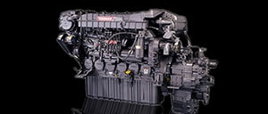 Propulsion Engines (High Speed)
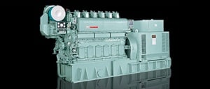
 Propulsion Engines (Medium Speed)
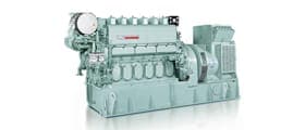
 Auxiliary Engines
 SCR System
 Dual Fuel Engine
 Two-stage Turbocharging System
 Electric Propulsion System
 Energy Systems
 Compact Equipment
 Industrial Engine
 Power Generation
 Compact Power Products
Research & Development Center
YANMAR Technical Review
A Study of Gas-Diesel Dual Fuel Combustion for Higher Thermal Efficiency and Lower Emissions
Abstract
The dual fuel combustion of a lean homogeneous gas mixture ignited by micro diesel injection has the potential to realize low emissions and high thermal efficiency. The research described in this report focused on the effects of gas composition on the combustion characteristics. The diesel engine was tested using a variety of gas fuels, including hydrogen (H2), carbon monoxide (CO), methane (CH4), and mixtures of these, and the fundamental combustion characteristics of each gas were obtained. This report reviews the optimum gas compositions in terms of ignitability and degree of constant volume, for the various engine operating conditions that were obtained from these results.
1. Introduction
Since diesel engines deliver high economical performance, they are widely used to power automobiles and various types of industrial machinery. However, they are facing stringent requirements for reducing emissions, such as nitrogen oxides (NOX) and particulate matter (PM). In diesel combustion, due to the wide range distribution of the air-fuel ratios during the combustion process, NOX (being produced in localized regions of high temperature) and PM (being produced in regions of excess fuel) are produced almost simultaneously(1). Although numerous efforts have been made to reduce emissions by achieving lean-homogeneous combustion by optimizing the mixture formation process(2)(3), it is still challenging to apply this over a wide range of operation conditions due to the difficulties of ignition control. The author has previously studied a fuel reformation engine system which reforms the diesel fuel into gasified fuel such as hydrogen, carbon monoxide, or methane, and ignites this lean mixture by using micro-pilot diesel injection(4). The gaseous fuels which have low ignitability can prevent early ignition at the compression stroke, and the direct injection of diesel fuel which has high ignitability at TDC can control precise ignition timing across the entire range of engine operations. On the other hand, the need to reduce carbon dioxide (CO2) emissions has also directed attention in recent times toward gasification technologies which convert woody biomass, a carbon-neutral fuel, to light gas to be supplied to internal combustion engines(5). In both cases, how to achieve the best dual fuel combustion, i.e. the seeking of the best combination of the gasified fuel properties at each engine operating condition, is the key to achieving high efficiency and low emission.
Based on this background, this report describes the experimental evaluation of the effect of the pre-mixed gas composition on the combustion performance of gas-diesel dual-fuel engines. Further, it describes the results of a consideration of the optimal gas properties under different engine operating conditions.
2. Experiment Apparatus and Method
2.1. Test Engine
Table 1 shows the specifications of the test engine, and Figure 1 shows a diagram of the experiment apparatus used in this study. The engine is a direct-injection diesel engine with a common-rail fuel injection system (CRS) and is able to inject diesel fuel into the cylinders at any crank angle. It has also been modified to introduce the gas fuel at the upstream of the intake manifold to form the lean homogeneous gas mixture. The intake air is pressurized by an electrical compressor, and a surge tank is provided in the intake system to minimize the pressure fluctuation from the compressor. The gas pressure in the intake manifold is controlled by a pressure regulator and the intake throttle.
2.2. How Gas Fuel is Supplied
Hydrogen, carbon monoxide, and methane were used as the gas fuels for experimental testing. The gases were supplied from pressurized cylinders via a primary regulator at approximately 0.6 MPa, through the flow control valves operated to achieve the desired gas composition, and introduced into the gas mixing tank to form a uniform mixture. The mixed gas was then taken from the tank via a secondary regulator at a pressure of 0.3 MPa and supplied to the engine at a flow rate determined by a flow control valve located at the upstream of the intake manifold. The gas composition in the mixing tank was analyzed by using a gas chromatograph each time the test gas was changed to determine the actual composition of the gas supplied to the engine.


2.3.Experiment Method
Table 2 shows the experiment conditions. The engine was operated at a constant speed of 1000 min-1 under low, medium, and high loads (with a brake mean effective pressure (BMEP) of 0.12 MPa, 0.48 MPa, and 0.84 MPa, respectively).
First, to determine the engine operating conditions at which the engine was able to run continuously without cylinder over-pressure or misfiring, the engine was operated at constant power output while varying the amount of gas fuel supplied and the diesel injection start timings. Initially, hydrogen (H2), carbon monoxide (CO), and methane (CH4) were tested individually to assess the effects that different gas compositions had on gas-diesel dual-fuel combustion performance. Next, tests were conducted using mixtures of carbon monoxide and hydrogen, and methane and hydrogen. All cylinder pressures were monitored during testing, and the operational limits were determined by identifying the conditions at which cylinder pressure exceeded the limit, early ignition occurred, or significant combustion variability was observed (in case of misfiring). An intake pressure equivalent to natural aspiration (N/A) was selected as the default condition, and testing with variable intake pressure were only conducted for tests with variable air excess ratio of the pre-mixed gas.

2.4. Definition of Combustion Performance Indicators
The following indicators were defined to evaluate the experiment results in this report.
(1) GFER
The gas fuel energy ratio ( ) is defined as the proportion of the energy supplied to the engine accounted for by the gas fuel. The value is obtained from the measured gas flow rate and diesel injection quantity using equation (1). Here,
  and
and  represent the amount of energy provided by the gas fuel and diesel respectively, and obtained by equations (2) and (3).

Here,  and
and  are the measured mass flow rates for the gas fuel and diesel respectively, and
  and
and  are lower heating values. In the case of the mixed gas fuel, the value of is obtained by apportioning the lower heating values of each fuel in proportion to their respective mol fractions measured by gas chromatography.
(2) Ignition delay
Ignition delay ( ) is used as an indicator of ignition performance and is defined as the crank angle between the beginning of the injection signal and the point at which the rate of heat release (RoHR) turns positive.
(3) Combustion duration and combustion duration ratio
Combustion duration ( ) is used to determine the relative combustion speed and is defined as the crank angle between ignition and the cumulative amount of RoHR reaching 90% of the total. This is then used to calculate the ratio of combustion duration (
 ) by dividing by the combustion duration for diesel fuel under otherwise identical conditions (
 ), as shown in equation (4).

3. Experiment Results
3.1. Operating Limits when Using Diesel and One Other Gas
Figs. 2 (a)-(c) show the operating limits when diesel is used with one of hydrogen, carbon monoxide, or methane.

In the case of diesel and hydrogen (Fig. 2(a)), the increased cylinder pressure that results from a higher GFER at high load (BMEP = 0.84 MPa) causes a narrowing of the operating range when the injection timing is advanced. Also, early ignition occurred at GFER above 50%. The operating range also becomes more restricted as the injection timing is advanced when operating at medium load (BMEP = 0.48 MPa), but in this case the engine can operate at more than 90% GFER. At low load (BMEP = 0.12 MPa), advancing the injection timing does not impose any restrictions, while the operating range when injection is retarded is largely the same as for diesel combustion.
In the case of diesel and carbon monoxide (Fig. 2(b)) or methane (Fig. 2(c)), the higher GFER causes a narrowing of the operating range when at high load (BMEP = 0.84 MPa), as observed for hydrogen. However, by providing the appropriate ignition timing, the engine can operate at GFER of more than 90% without early ignition. At medium load (BMEP = 0.48 MPa), the operating range becomes wider when the injection timing is advanced and the GFER is high. This is due to the slower combustion speed compared to conventional diesel combustion, resulting in a lower maximum cylinder pressure for the same injection timing. At low load (BMEP = 0.12 MPa), a narrowing of the operating range occurs for retarded injection timings, with the engine becoming more unstable at high GFERs for both carbon monoxide and methane.
Fig. 3 shows the ratio of combustion duration () for different gas fuel energy ratios (), at the same diesel fuel injection timing (TDC). At high load (BMEP = 0.84 MPa), the higher GFER results in an RoCD of 1.0 or less for all gases, meaning that the combustion period is reduced compared to that of diesel combustion. At high load with a high GFER, the air excess ratio of the pre‐mixed gas is lower, resulting in faster combustion speed. At medium load (BMEP = 0.48 MPa) when using hydrogen, as with high load, the RoCD falls as GFER increases. However, the RoCD increases for the other gases. At low load (BMEP = 0.12 MPa), RoCD increases at high GFERs for all gases. These results can be explained by the slowing of the combustion speed due to increase of the air excess ratio at lower load.
Based on the results, it can be concluded that the main challenges of the gas-diesel dual-fuel combustion are to prevent the early ignition at high load and to keep a higher degree of constant volume against the slowing of combustion speed at high air excess ratio.

3.2. Influence of Excess Air Ratio on Degree of Constant Volume Combustion
Fig. 4 shows the relationship between RoCD and air excess ratio for each pre-mixed gas fuel when operating at medium load (BMEP = 0.48 MPa). Regardless of gas composition, RoCD decreases with the reducing air excess ratio. This indicates that the degree of constant volume can be improved by reducing air excess ratios. However, excessive intake throttling to reduce the excess air ratio causes the increase of pumping losses. To improve thermal efficiency through optimization of the air excess ratio requires a balancing of improvements in the degree of constant volume combustion against the higher pumping losses.

3.3. Influence of Hydrogen on Degree of Constant Volume Combustion
To investigate the changes in combustion characteristics that resulted from adding hydrogen to the two other (comparatively slow-combusting) gases, hydrogen being the easiest to ignite and fastest combusting of the three. Fig. 5 and 6 show graphs of the gas fuel energy ratio () and ratio of combustion duration () for a number of mixtures (containing different proportions of hydrogen) of carbon monoxide and hydrogen and of methane and hydrogen respectively.
At high load (BMEP = 0.84 MPa), adding hydrogen to carbon monoxide (Fig. 5) increases the rate of combustion, such that at hydrogen percentages of 50% or more, it significantly reduces the maximum GFER at which the engine is able to operate due to the limit on cylinder pressure. Similarly, at medium load (BMEP = 0.48 MPa), RoCD shows a notable fall off as the percentage of hydrogen increases when the GFER is high. The RoCD also falls as the percentage of hydrogen increases when adding hydrogen to methane (Fig. 6). However, for all loads, the change in RoCD was smaller than that when hydrogen was added to carbon monoxide. This indicates that there is not a simple relationship between the amount of hydrogen and improvements in the degree of constant volume. Rather, it indicates that the effect also depends on what gas the hydrogen is mixed with.


3.4. Evaluation of Ignition Control Performance
Fig. 7 shows a plot of ignition delay () at various fuel injection timings and gas components. The graph shows the ignition timing remaining mostly within a fixed band, with instances of early ignition occurring only at high load when using diesel with 100% hydrogen gas. In other words, it indicates that the risk of early ignition is low unless using a gas that contains a very high proportion of hydrogen, and that ignition control of pre‐mixed gas is possible by using diesel micro-pilot injection.

4. Optimal Gas Composition in Terms of Engine Output
Fig. 8 shows the factors that influence the optimal gas composition with respect to output (load) for gas-diesel dual-fuel combustion with various gas compositions. The horizontal axis of the graph represents the percentage of methane and hydrogen (or mixed gas of hydrogen and carbon monoxide) in the gas fuel, and the vertical axis is the brake mean effective pressure (BMEP).
At high loads when the air excess ratio ( ) of the pre‐mixed gas is low and the temperature in the cylinder is high, it is desirable to reduce the amount of hydrogen in the supplied gas as much as possible to minimize the risk of excessive cylinder pressure or early ignition. Further, it is desirable to use methane as the main gas because the combustion speed and ignitability are relatively lower even when mixed with hydrogen. At partial loads, to prevent misfiring and maintain a high degree of constant volume, it is desirable to use hydrogen, or a gas with a high percentage of carbon monoxide which can be mixed with hydrogen to increase combustion speed. Moreover, to achieve an optimal excess air ratio at each operating condition, supercharging at high loads and intake throttling at medium and low loads can be used.

5. Conclusions
Prompted in part by the rapidly developing shift toward electrification in the automotive market, numerous passenger vehicle OEMs have announced the withdrawal of diesel-engine vehicles from the European market, a trend that is forecasted to extend to off-road engines in the future. Despite this, diesel engines with their "omnivorous" ability to use different fuels, can also serve as a useful tool for reducing CO2 emissions by utilizing energy that might otherwise go unused. As such, by making improvements to their emissions performance, and thereby overcoming their major deficiency, it is believed that these engines can continue to contribute to the future development of society. This study is only the beginning of the work towards achieving this, and numerous challenges still remain before the technology can be put into practice. In the future, Yanmar intends to continue looking more deeply into the technology so as to contribute to a better society through the knowledge that is created.
References
- (1)Kamimoto, T. et.al.: High Combustion Temperature for the Reduction of Particulate in Diesel Engines, SAE Technical Paper (1988), 880423
- (2)Naoya Ishikawa, "Study of Pre-mixed Compression Ignition Combustion on Multi-cylinder Diesel Engine", Transactions of Society of Automotive Engineers of Japan, Vol.37, No.4, p.155-160 (2006)
- (3)Michio Nakano, "Combustion Characteristics and Ignition Control of Homogeneous Charge Compression Ignition Engines", Transactions of Society of Automotive Engineers of Japan, Vol.38, No.3, p.37-42 (2007)
- (4)Go Asai, "Diesel Fuel Reformation by Piston Compression of Rich Mixture", Transactions of Society of Automotive Engineers of Japan, Vol.49, No.1, p.24-29 (2018)
- (5)Satoshi Hirata, "Gasification Combined Heat and Power System of Woody Biomass," Journal of The Society of Instrument and Control Engineers, Vol.45, No.10, 2006
-IMPORTANT-
The original technical report is written in Japanese.
This document was translated by Research & Development Management Division.
Author
