 Agriculture
 Recreational Marine
 Recreational Boat
 Premium Cruiser
 Marine Equipment
 Marine Commercial
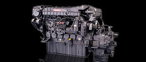 Propulsion Engines (High Speed)
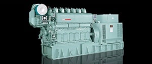
 Propulsion Engines (Medium Speed)
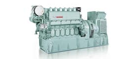
 Auxiliary Engines
 SCR System
 Dual Fuel Engine
 Two-stage Turbocharging System
 Electric Propulsion System
 Energy Systems
 Compact Equipment
 Industrial Engine
 Power Generation
 Compact Power Products
YANMAR Technical Review
Marine SCR System for Compliance with IMO NOX Tier 3 Regulations
Abstract
The International Maritime Organization's (IMO) NOX regulations first came into effect in 2000, with the more stringent Tier 3 regulations being introduced from 1st January 2016. Tier 3 requires a reduction in NOX emissions of 80% relative to Tier 1. Yanmar chose to use a SCR system to comply with the new rules, developing engines fitted with SCR systems in-house. The initial step involved research of the core technologies required, which was undertaken through participation in a national project. This was followed by bench tests and ship-based durability tests. The end result was the commercial release of Yanmar's first marine SCR systems. This article describes the features of the SCR systems used for large marine engines.
1. Introduction
The Tier 3 NOX emissions regulations (IMO3) of the International Maritime Organization (IMO) that came into force on January 1, 2016 stipulate an 80% reduction in emissions relative to Tier 1 (but do not apply retroactively). IMO3 regulations apply in designated sea areas referred to as NOX Emission Control Areas (N-ECAs). Coastal waters of the United States and Canada already have this designation, with the North Sea and Baltic Sea to be added from January 1, 2021 (Fig. 1).
Selective catalytic reduction (SCR) includes injecting urea water into the exhaust gas and using the exhaust gas heat to produce ammonia (NH3). This is then reacted with the NOX on a catalyst to break the NOX down into harmless nitrogen and water. SCR can operate as a standalone technology (not requiring any additional devices), and is able to reduce NOX by 80% or more. It is already widely used on land due to its high level of reliability and durability. Another reason behind Yanmar's choice to use SCR for compliance with IMO3 was that it does not require significant engine modifications.
This article describes the development of Yanmar's first-ever SCR system for large marine diesel engines and the main characteristics of the system. It also discusses how Yanmar intends to deal with SOX regulations.

2. Principles of SCR
SCR uses urea water, (solid urea (H2N-CO-NH2) dissolved in water) as its reducing agent. With marine engines, it is common to use urea water with a 40wt% concentration because the temperature in engine rooms does not fall below freezing temperatures and to save storing space.
When urea water is injected into exhaust gas, a process of water evaporation → dissolution of solid urea → thermolysis occurs (Fig. 2 (1)). Furthermore, hydrolysis of isocyanic acid (HNCO) occurs on the catalyst ((2)), resulting in the production of 2 mols of NH3 from 1 mol of urea ((1) + (2)). On the catalyst, the NH3 selectively reduces the NOX, breaking it down into harmless nitrogen and water. The reduction reaction occurring on the catalyst can be standard, fast, or slow, depending on the NO/NO2 ratio of the NOX. For medium- to high-speed marine engines, the majority of NOX is NO, so the standard reaction is dominant in almost all cases ((3)).
There are multiple SCR catalysts available, each with a different main chemical components. In the case of marine engines, which use fuel with a relatively high sulfur concentration, vanadium-based catalysts are used because of their resistance to sulfur poisoning (see photograph in Fig. 2). With SCR, there exists a region in the relationship between fuel sulfur concentration and exhaust gas temperature where acidic ammonium sulfate precipitation occurs, as shown in the graph in Fig. 2(1). Because acidic ammonium sulfate clogs the catalyst and lowers the NOX reduction rate, it is necessary to keep the exhaust gas at an appropriate temperature (at the SCR inlet).

3. Development of Yanmar SCR
3.1. Development of Fundamental Technology
Full-scale development of the SCR system for marine engines began with participation (in 2007) in the Super Clean Marine Diesel (SCMD) Project sponsored by the Ministry of Land, Infrastructure, Transport, and Tourism. Since then, Yanmar has continued with proprietary system development (Fig. 3). Phase I of the SCMD Project focused on fundamental technology development and involved using actual engines to evaluate the steady-state performance of the catalyst selected on the basis of element test results and to optimize the urea water injection method. This included improving NOX reduction performance and building the core system. Phase II involved the planning of on-board tests to evaluate operations and durability under actual use conditions. As on-board tests are only possible by installing an SCR system on a client's ship, it is essential that any impact on ship operations be avoided. To this end, a durability testing devices were installed at the Yanmar Kota Kinabalu R&D Center located in Malaysia to ensure that sufficient land-based evaluation had been conducted before shifting to on-board testing. The result, as shown in Fig. 4, was that the system achieved its target performance (NOX reduction rate of 80% or higher). On-board testing also proceeded smoothly without any problems. The combined 9,000 hours of operation for land-based and on-board reliability and durability validation provided an invaluable opportunity not only to produce a more complete SCR system, but also to gain significant knowledge prior to commercialization.


3.2. Product Specification Development
The products for specific auxiliary engine models had been developed based on second on-board test used a full system (see Section 4.2) designed using the technology and knowledge gained from the SCMD project as well as the results of later land-based durability tests conducted under actual use conditions such as low exhaust gas temperature and other parameters. This process of developing specifications for the various engine models included the use of fluid analysis software to optimize specifications. The same software was also used when evaluating specifications for the on-board tests. Fig. 5 is an example of this analysis results, showing performance predictions based on NOX reduction characteristics for changes to the shape of the catalyst reactor inlet duct that shortened its overall length. As no significant differences were observed between the two cases, the dimensions of the inlet duct were finalized and the system validated under actual use conditions. In this way, the work included the establishment of simulation-based performance prediction methods for shortening the development time.

4. Characteristics of Yanmar SCR System
4.1. Catalyst Reactor
As noted in the introduction, compliance with the IMO Tier 3 regulations for NOX emission levels (80% reduction relative to Tier 1) is required when operating in N-ECAs. Outside these areas, the Tier 2 levels apply (20% reduction relative to Tier 1). In most cases, marine engines run on low-grade fuels, meaning that exhaust gases contain high levels of combustion residue and SOX. One way of dealing with this would be to bypass the catalyst reactor outside N-ECAs to prevent deterioration of the catalyst due to exposure to exhaust gases, only operating the SCR system while inside an N-ECA. However, such an operating practice would require a way for the exhaust gas to bypass the catalyst reactor, doubling the amount piping required and thereby making installation more difficult, particularly in ships with multiple engines.
To address this, Yanmar set out to reduce total system size by making the bypass channel smaller, devising the integrated bypass and catalyst reactor unit shown in Fig. 6. This design also takes account of safety considerations, with the urea water injection nozzle being located downstream the exhaust gas pipe branch to prevent ammonia from leaking into the bypass channel in the unlikely event of a switch valve failure. Another reason for using a bypass channel was to minimize the increase in engine back pressure outside N-ECAs, which is where ocean-going ships spend most of their time.

4.2. System Design for Multi-Unit Installation
Ships typically have more than one auxiliary engine, with each engine needing its own catalyst reactor, urea water injection nozzle, and nozzle injection on/off control unit ("Nozzle unit"). In response, Yanmar designed a simple system in which the SCR control panel and urea water circulation pump are each consolidated into a single unit. This design requires less engine room piping and wiring (Fig. 7) and also helps reduce the amount of work required at the shipyard.
The SCR control panel continuously monitors the engine and SCR system status, with all functions being performed automatically based on operating conditions. This makes operation easier for the user, only requiring the operation of the ECA IN/OUT switch on the control panel as the SCR operation.
For the urea injection, a simple map control method is used that does not require a NOX sensor. The amount of NOX emitted from the engine varies greatly, depending on atmospheric conditions. The Yanmar SCR system is equipped with a temperature and humidity sensor, and a method for predicting accurately this continuously changing amount of NOX in the engine exhaust was established by using data specific to each engine model gained from bench tests. This improves NOX reduction performance and prevents excessive emission of ammonia (ammonia slip).

5. Product Range
Table 1 lists the SCR models and equipment used for respective engine models. Despite having eight different models of engine available in approximately 100 different variations, a focus on standardization of the SCR control panels succeeded in limiting the number of panel types to four, for use with one through four engines respectively. For a given number of engines, the same control panel hardware can be used regardless of whether for 6EY18 or 8EY33 engines. This is expected to significantly improve productivity in SCR control panel manufacturing. Differences in engine specifications are handled by changing the SCR control panel settings, a feature that was made possible by standardizing the internal equipment configurations of each unit connected to the control panel. In the case of the urea flow rate control valve, for example, standardization involved first looking for a supplier able to provide a wide range of flow rate options, and then working together with them on unit testing, ultimately resulting in the selection of a single pump unit and five types of Nozzle unit. This standardization is expected to significantly improve productivity and reduce management overheads for the overall system.
Table 1 SCR Product Range

6. SCR and Compliance with SOX Regulations
As with NOX, regulation of SOX is also becoming stricter (see Fig. 8, with the regulations applying retroactively). The levels of permitted emissions are defined in terms of the concentration of sulfur in the fuel being used, with different limits applying in designated sea areas known as SOX Emission Control Areas (S-ECAs) and elsewhere (GLOBAL).

In October 2016, the IMO passed a resolution lowering the upper limit on sulfur concentration outside S-ECAs from 3.5% to 0.5%, beginning from January 1, 2020. The following two methods are commonly used for complying with SOX regulations.
- Use low-sulfur fuel to prevent SOX emission. (Fuel-based compliance)
- Combine use of low-quality fuel with a scrubber device (Fig. 9) to eliminate SOX. (Exhaust gas after treatment)

Ship owners and shipbuilders are currently expediting their studies of compliance options, with factors being considered including trends in the prices and availability of low-sulfur and high-sulfur fuels, and the initial and running costs for scrubber systems. Various combinations of SOX reduction and SCR types and operation are shown in Table 2. Yanmar intends to offer appropriate SCR specifications and operating capabilities to ensure that users are able to choose from among these variations.
Table 2 SOX Reduction and SCR for Overseas Ships

7. Conclusions
Since supplying its first commercial SCR system to a Korean shipbuilder in 2015, Yanmar had delivered 50 systems as of December 2017, with orders for more than 170 units received in total. While most of these systems have been supplied for auxiliary engines used on ocean-going ships, Yanmar has also taken advantage of the ability to consolidate the peripheral system control equipment into a single unit to supply a set of main and auxiliary engines for a training ship used by a fisheries high school in Japan.
Meanwhile, a wider range of specifications and further downsizing of the catalyst reactor will be needed to comply with tightening emission regulations, including SOX regulation and the designation of European sea areas as N-ECAs in 2021. Moving forward, Yanmar intends to continue working to identify market trends and customer needs to provide optimal SCR systems.
8. References
- (1)Sasaki, Kjeld Aabo, Journal of the Japan Institute of Marine Engineering, Vol. 43, No. 3 (2008)
-IMPORTANT-
The original technical report is written in Japanese.
This document was translated by Research & Development Management Division.
Author
Development Division
Large Power Production Management Division
Power Solution Business
Tsuyoshi Inoue
Development Division
Large Power Production Management Division
Power Solution Business