 Agriculture
 Recreational Marine
 Recreational Boat
 Premium Cruiser
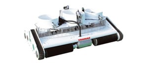 Marine Equipment
 Marine Commercial
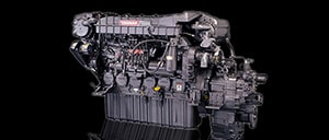 Propulsion Engines (High Speed)
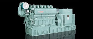
 Propulsion Engines (Medium Speed)
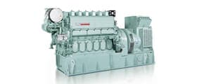
 Auxiliary Engines
 SCR System
 Dual Fuel Engine
 Two-stage Turbocharging System
 Electric Propulsion System
 Energy Systems
 Compact Equipment
 Industrial Engine
 Power Generation
 Compact Power Products
Research & Development Center
Research & Development Unit
YANMAR Technical Review
Development of Zero Emission Generating System "Stirling Engine"
Abstract
The power-generating technology which does not emit CO2 at all (Zero Emission) leads to realize Yanmar Brand Statement “A SUSTAINABLE FUTURE”.
Not only energy-saving technologies, but also Zero Emission technologies using renewable energy such as solar and wind power are focused recently. The stirling engine is the one of the Zero Emission technologies which convert waste heat energy to electricity with high efficiency while it does not emit CO2 at all. However due to several problems of reliability, few manufactures succeed in commercialization in the world. Our purpose is to establish reliability of stirling engine generating system which can provide Zero Emission electricity. This article describes the development of Stirling engine generating system.
1.Introduction
Realizing the goal expressed in Yanmar's brand statement of "A SUSTANABLE FUTURE" requires not only reductions in CO2 emissions but also high-performance energy conversion technologies with zero CO2 emissions.
As the problem of warming continues to worsen year-by-year throughout the world, there is a need both for the adoption of energy-efficient technologies that reduce electric power consumption and CO2 emissions and for zero-emission power sources such as photovoltaic, wind, and other forms of renewable energy. One new form of zero-emission generation that is attracting interest is the production of electric power from unused thermal energy, such as exhaust heat that has gone unused in the past. While the Stirling engine is known for its ability to perform this conversion, it suffers from a number of technical issues, including reliability, and as a result there have been few instances of its commercialization anywhere in the world. Yanmar has developed a Stirling engine with the aim of producing electric power with zero emissions. This article describes the features of this zero-emission Stirling engine generating system and the associated technologies developed.
2.Features of Stirling Engines
2.1 Principle of Operation
This section describes the basic mechanisms and operation of what is typically called a β Stirling engine. As shown in Fig. 1, a β Stirling engine has a single cylinder containing a displacer piston and a power piston that are connected to the crankshaft with a 90° phase difference. The space above the displacer piston and the space above the power piston (named as expansion space and compression space respectively) are linked via three heat exchangers (heater, regenerator, and cooler), and this allows the working gas to move back and forth between the two spaces. Stirling engines typically use helium or hydrogen as their working gas, taking advantage of the high thermal conductivity of these gases.

Fig.2 shows the principle of engine operation, which is explained in terms of states 1 to 4 in the cycle diagram on the left. When the displacer piston is close to the top of its stroke, the power piston is rising, thereby compressing the working gas in the compression space (1→2). The working gas flows from the cooler to the regenerator and then to the heater where it takes in heat. Next, as the displacer piston begins to fall, low-temperature working gas is drawn into the heater where it is heated, raising the temperature and pressure in the spaces (2→3). The pressure change propagates throughout the spaces at the speed of sound, and the pressures in the expansion space and compression space become almost the same. Driven by this pressure, the power piston begins to fall, thereby doing work by expansion (3→4). Finally, the displacer piston begins to rise again, causing working gas to flow from the heater to the cooler, returning it to its initial cooled state (4→1). While the theoretical thermal efficiency of the Stirling cycle is very high, being the same as that of the Carnot cycle, the efficiency achieved in practice is less due to the pressure and thermal losses in the engine. Nevertheless, if these various losses can be reduced, the potential exists for achieving high thermal efficiency.

2.2 Forms of Heat Transfer for Unused Heat(1)
Utilization of unused heats such as the heat of exhaust gas requires to extract the heat through a heat exchanger (heater pipes). This section describes two types of heat transfer, convective and radiative heat transfer.
An example of multi-tubular heat exchanger used to perform convective heat transfer is shown in Table 1. Key heat exchanger parameters include the length, number and layout of heater pipes. Obtaining maximum heat exchange performance involves optimizing these parameters to increase the heat transfer surface area without reducing the mean flow rate of the exhaust gas that passes over the outside surfaces of the heater pipes. Moreover, because the exhaust gas may contain corrosive dust, anti-corrosion measures are also needed, such as surface modifications of the heater pipe and ways of removing any dust that adheres.
One way to avoid problems like this of heater pipe corrosion or clogging is to encase the heater pipes in a protective cover. The form of heat transfer to the heater pipes in this case is the radiative heat transfer shown in Table 1, with the energy radiated from the protective cover being absorbed by the outside surfaces of the heater pipes. Having air inside the protective cover, however, results in a high thermal resistance due to its heat insulating effect. The effective heat received from radiated energy is determined by the Stefan-Boltzmann law, and it is proportional to the difference between the fourth power of protective cover inside surface temperature and the fourth power of heater pipes outside surface temperature, and also to the radiative surface area, which in this case is the inside surface area of the protective cover. As this requires a larger heat transfer area than convective heaters, its use is dependent on the heat source having a high temperature and on being able to provide sufficient radiative surface area.
While the two different forms of heat transfer are explained, in practice it is important to conduct preliminary studies such as experimental testing, including thermal fluid analysis, as use of unused heat involves not only clean exhaust gas, but also thermal resistance being influenced by the presence of dust.
Table1 Different Forms of Heat Transfer and Example Heaters(1)

3.Development of Exhaust Heat Recovery Stirling Engine
Fig.3 shows a schematic diagram and photograph of a β Stirling engine. While the construction is the same as that in Fig. 1, placing annularly for the regenerator and cooler reduces pressure losses by providing a uniform flow of working gas. It also reduces the engine diameter because this annular layout for the regenerator and cooler results in a compact concentric configuration. β Stirling engine, however, requires the layout of the displacer piston and power piston with a 90° phase difference and the complex drive mechanism to convert the reciprocating motion to rotational motion on the extended line of the piston axis. What is wanted is a piston drive mechanism that is simple and capable of a long operating life. The methods conventionally used to allow two concentric pistons in the same cylinder are the crosshead, rhombic, and scotch yoke mechanisms. The scotch yoke mechanism is simpler than the rhombic and requires fewer bearings. The crosshead mechanism requires a long connecting rod to reduce sliding losses for the pistons. Accordingly, a scotch yoke mechanism was adopted for piston drive mechanism by reasons of simplicity and size. Fig. 4 shows an example of the scotch yoke mechanism.


Fig.3 Schematic diagram and Photograph of Exhaust Heat Recovery Stirling Engine

The crankshaft with two eccentric pins having an eccentricity corresponding to the piston stroke is made so as to provide the 90° phase difference between the displacer and power pistons. The crankshaft is placed through the long holes made within the yokes. The displacer and power pistons are connected to the yokes independently. A rod (called sliding rod) passes through linear bearings fitted at the ends of each yoke and the pistons reciprocate along these rods. The reciprocating motion of the pistons is converted to rotational motion through the long holes of the yokes and the crankshaft with eccentric pins. Because this design places a high load on the yoke, sliding rod, and crankshaft, measures are needed to ensure the reliability of drive components.
4.Development of Electric Power Generating System(1)
Fig. 5 shows an overview of the Stirling engine generating system using exhaust heat. A highly efficient interior permanent magnet (IPM) generator directly connected to the engine crankshaft is used to convert the rotational motion into electric energy. The output of this engine generator (voltage and current) varies with changes in the temperature and flow rate of the heat source. The engine is controlled by a programmable logic controller (PLC) built in the control panel. Even when the conditions of the heat source vary, the engine speed and generator output are controlled based on the amount of heat extracted from the Stirling engine heater (effective heat input). Matching the speed to the available heat as the heat source varies keeps the system operating in a way that avoids any significant reduction in generation efficiency. For routine operation, it is possible to build a generating system in which all operation, including startup, generation, and shutdown, are controlled automatically based on the measured condition of the heat source. The system converts the electric power to DC at the outlet of the generator control inverter and then converts it to AC200V using a regeneration inverter. This AC200V power is interconnected to the grid power system at the host site.

5.Example of Field Installation(1)
This section describes an example of the exhaust heat recovery Stirling engine of which heater is installed in a flue of the incinerator and using radiation as heat transfer. Fig. 6 and 7 show an example of installation at a general waste disposal facility which is used by local governments to burn waste collected from households and businesses in an incinerator and its photograph. The waste is burned at a high temperature of 800 to 1000°C in the furnace of the incinerator. To protect the Stirling engine heater from the corrosive dust present in the exhaust gas, it is fitted with a cylindrical protective cover. Thermal energy from the exhaust gas is partially transferred to the protective cover and then radiated from the inside surface of the cover to the outside surface of the heater pipes.
The heat recovery Stirling engine can be installed on the wall of the incinerator by inserting the heater using holes provided for this purpose in the refractory bricks on the wall. In the example, the heater is inserted horizontally to facilitate the installation of the engine on the incinerator side wall. Because it can be installed in the high-temperature empty spaces, which include the furnace side walls, ceiling, and flue of the incinerator, multiple Stirling engines can be operated on a single incinerator.


6.Conclusions
The use of a Stirling engine to generate electric power from unused thermal energy is a generating system with zero emissions of CO2. Yanmar intends to fulfill its goal of creating “A SUSTAINABLE FUTURE” to achieve a better future and more prosperous life by pursuing higher efficiency and performance and recovering electric power from previously unused exhaust heat around the world and supplying zero-emission electric power to customers with the minimal impact on the environment.
7.References
- (1)Akazawa, "Development of Stirling Engine Power Generation System Using Exhaust Heat", Journal of the Japan Institute of Marine Engineering, Vol. 51, No. 1, p102-109 (2016) in Japanese.
-IMPORTANT-
The original technical report is written in Japanese.
This document was translated by Research & Development Management Division.
Author


Research & Development Center
Research & Development Unit
Keiichiro Yuzaki

Solution Center
Research & Development Unit