 Agriculture
 Recreational Marine
 Recreational Boat
 Premium Cruiser
 Marine Equipment
 Marine Commercial
 Propulsion Engines (High Speed)
 Propulsion Engines (Medium Speed)
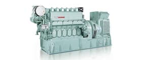
 Auxiliary Engines
 SCR System
 Dual Fuel Engine
 Two-stage Turbocharging System
 Electric Propulsion System
 Energy Systems
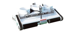
 Compact Equipment
 Industrial Engine
 Power Generation
 Compact Power Products
YANMAR Technical Review
TRIBOLOGY for Product Reliability and Safety (Application of TRIBOLOGY Technology to Improve Reliability of Air Conditioner Compressor)
Abstract
TRIBOLOGY is defined as "The science and technology of interacting surfaces in relative motion and of related subjects and practices" according to the glossary of the OECD. And it is also an engineering field that deals with friction, wear, and lubrication.
As there are many parts which works in sliding motion, TRIBOLOGY is an essential technology for ensuring reliability and durability of Yanmar products.
In this article, the study case of the reliability improvement of the compressor installed in a gas engine heat pump system is introduced applying experimental and theoretical analysis techniques of TRIBOLOGY. Specifically, operating conditions which makes insufficient lubricating condition were identified through experiments using an electrical measurement method of surface contact ratio. Furthermore, the oil film thickness at vane top was calculated using a theoretical analysis to clarify the mechanism of the insufficient lubrication.
1.Introduction
An OECD glossary defines tribology as “the science and technology of interacting surfaces in relative motion and of related subjects and practices”. In other words, tribology is knowledge about surfaces and their vicinities that are in sliding contact with each other, and technologies for sliding smooth and for preventing surface wear.
Mechanical devices include numerous parts in sliding contact, with products made by Yanmar being no exception. As technologies for ensuring smooth sliding help improve the reliability and durability of these machines and reduce their fuel costs, tribology is currently a subject of much interest.
This article presents examples of the use of experimental techniques from tribology together with theoretical analysis techniques to improve the reliability of the compressors used in gas engine driven heat pump systems (hereinafter referred to as GHPs). Specifically, it reports the results for clarifying the lubrication mechanism by measuring the variations of lubrication with operating condition of actual GHPs compressor using a contact resistance method that measures and quantifies the contact conditions of sliding parts and by theoretical analyses.
2.Compressor and GHP system under test
2.1.Compressor
Fig. 1 shows the structure of the multiple vane compressor used in this research. Unlike rotary compressors (which also use vanes), multiple vane compressors are able to operate at high speed because they minimize an unbalanced rotational force with the co-axial arrangement of the cylinder and rotor. Accordingly, they are widely used in such applications as vehicle air conditioning and GHPs because of their small size, large capacity, and low vibration.

Due to their high operating speeds, as noted above, a feature of multiple vane compressors is the high slip speed of the vane tops. If the lubrication of the region of contact between the vane tops and cylinder is inappropriate, it can be very detrimental to the performance of the air conditioner, including excessive wear and the generation of large amounts of abrasion particles leading to clogging of the compressor’s lubricating oil supply pipes.
As the compressor is the only component in refrigeration cycle equipment with parts in sliding contact at high loads and speeds, ensuring the reliability of the compressor extends the life of the air conditioner. For this reason, maintaining good lubrication of the vane tops is an important subject for these multiple vane compressors.
Dimensions of the compressor are shown in the figures. In this case, the rated capacity of the compressor is sufficient for air-conditioning of a 58m2 room.
2.2.Air Conditioning System
The lubrication of a compressor is significantly influenced by its operating conditions. Likewise, the compressor operating conditions vary widely in practical use due to factors such as the internal and external temperatures and the air conditioning preferences of the users.
A special compressor of which vane top lubrication can be measured was installed into a GHP air conditioning system as shown in Fig. 2 to measure the lubrication at the actual market operation conditions.

3.Experimental Analysis
3.1.Measurement of Lubrication by Contact Resistance Method
Because surface roughness and microstructure change at the sub-micron/nano meter level, quantifying the condition of lubrication in the region of contact between two sliding surfaces is difficult. No commercially available instruments exist that can measure the absolute distance at the accuracy of sub-micron/nano meters. Furthermore, there are risks that additional machining of a vane top for the measurement may interfere and actual phenomena occurred in this small distance cannot be measured. On top of this, the compressor vane to be measured in this study has a thickness of approximately 3 mm, making it particularly difficult to attach a sensor.
The contact resistance method shown in Fig. 3 was adopted to measure the lubrication between the vane top and cylinder surface. This method uses changes in electrical resistance to determine the degree of surface contact between the vane top and cylinder. This avoids the need to modify the vane top and cylinder surface in any way. However, because the parts other than the vane top and cylinder surface need to be electrically insulated, ceramic, plastic, and other insulators were used for this purpose at the required locations.

Fig. 4 shows how the results of contact resistance measurements were evaluated. When there is good lubrication between the vane top and cylinder surface (that is, when a sufficient thickness of oil film is present between them), the voltage applied between the vane top and cylinder surface remains and the measured voltage is equal to the applied voltage. When lubrication is not good and oil film formation is insufficient, on the other hand, the resistance goes to 0Ω. The applied voltage is grounded through the vane, resulting in a measured voltage of 0V. Accordingly, the contact resistance method quantifies the degree of lubrication between the surfaces with the measured voltage varying between 0V and the applied voltage. The applied voltage was 200mV. In this study the ratio of the measured voltage to the applied voltage is defined as “separation degree” (SD) expressed as a percentage. This quantifies the degree of oil film formed on the vane top.

3.2.Variation in SD over Cycle
The rotor angle represents the position of the vane top, with the angle at which the vane top passes the minor axis of an elliptical cylinder being defined as 0°. Fig. 5 shows how the SD varies through a compression cycle of the pressure chamber on the front side of the vane, which is consisting of suction, compression, and discharge periods. As indicted by the figure, the lubrication is worsened from the midway of compression period after the rotor angle passes 90°. As this correlates with the wear found on used compressors in the market, the validity of this measurement method is proved. A rotor angle of 90° is where the vane top passes through the major axis of the elliptical cylinder. From this angle, the vane top is pressed by the cylinder surface to slide into the vane slot in the rotor shaft.

3.3.Lubrication under Practical Operating Conditions
To reproduce the lubrication under practical operating conditions, the compressor for measurement was installed in a GHP air conditioning system and the vane top SD was measured for a total of 36 different sets of conditions (six sets of temperature and humidity conditions specified in JIS B 8627 that cover the range likely to occur in practical use × six different air conditioning capacities). Fig. 6 shows the measurement results. These results are shown on the figure as circles with diameter proportional to the average separation degree (ASD), where ASD is defined as the mean value of SD for rotor angles from 90° to 150° in recognition of the fact, noted above, that the lubrication is worsen during this compression period. The compressor operating conditions such as rotor speed and suction pressure of a GHP in practical use vary widely in accordance with the GHP’s control methods such as avoidance of high pressure due to the pressure limit for piping. Accordingly, the ASD values are plotted with suction pressure as the vertical axis and rotor speed as the horizontal axis.
The figure indicates that the vane top lubrication is worsened at high suction pressures and low rotor speeds. It can be readily assumed that this worsening of lubrication at low rotor speeds is caused by the decrease of ability for formation of a wedge-shaped oil film due to the lower oil catching speed at the vane top. In the case of high suction pressure, on the other hand, the mechanism for lubrication worsening is harder to identify given that, because the compression ratio decreases as higher suction pressure under constant discharge pressure, the load on sliding parts will also be lower when the suction pressure is high. In response, a theoretical analysis technique was established to calculate the lubrication mechanism for the vane top lubrication.

4.Theoretical Analysis
The theoretical analysis quantified the degree of lubrication by calculating the thickness at the vane top oil film.
4.1.Dynamic Model
The force ( ) with which a vane top presses against the cylinder surface is calculated from the equilibrium of forces acting on the vane. Fig. 7 shows the calculation model used for this purpose.
The forces in the y axis are those by the pressure difference between the pressure chambers to the front and rear of the vane  , where
  is the front-side pressure and
  is the rear-side pressure), and by the pressures of the compression chambers and at slot inlet and the oil pressure
  at the vane bottom ends for the vane side faces in the slot. During the compression period,
  becomes large and imposes a counter-clockwise moment on the vane in terms of the figure. This moment is balanced by the forces in the slot
  and
and  . During compression, the action of the moment tilts the vane right up and the vane moves to the right, forming a wedge-shaped oil film in the region acted on by . The moment due to the pressures and acting on the vane top is very small compared to the above-mentioned moment and then it is ignored.
The forces in the x axis is the force () at the vane top pressing the cylinder surface that is the sum of the following forces, the force due to the oil pressure (), the friction force in the region acted on by ( ), the friction force in the region acted on by (
 ), and the forces due to the pressure of the pressure chambers (
 ). The calculation was performed for a rotor angle of 100°, this being midway through the compression period where the lubrication is worsened found in the experimental testing.

4.2.Improvements to Theoretical Calculation
The only reported analysis of vane top lubrication in a multiple vane compressor is an experimental analysis by Numazaki et al.1). In the case of vane tops in the same type of rotary compressors widely used in electric heat pumps, Tanaka et al.2) and Ono et al.3) have undertaken analyses based on theoretical calculation using dynamic models like that described above. The initial calculations were conducted with reference to the boundary conditions and inputs used in these studies. The ratio of the oil film thickness calculated by theoretical analysis to the sum of the surface roughness of the vane top and cylinder is defined as "Oil film parameter" (OFP). The results are shown by the blue line in Fig. 8. As indicated by the figure, this shows the oil film thickness increasing with rising suction pressure, the opposite of the result obtained by experiment, in which ASD fell with rising suction pressure, indicating decreasing in oil film thickness.
Past calculation methods have assumed a constant 0.1 coefficient of friction without taking account of the variation of the lubrication between vane and slot in the region acted on by during the compression cycle. The viscosity of the vane top lubricating oil was calculated from the mean values of inlet and outlet temperature and pressure, without considering the change in ambient condition through the compression cycle. In contrast, for the lubrication at the slot in this study, variation of friction force taking account of partial contact by using mixed lubrication theory was considered. This theoretical calculation also used the viscosity calculated considering the solubility of the refrigerant into the lubricating oil, which is determined by the ambient temperature and pressure varying with rotor angle during compression. The purple and orange lines in Fig. 8 show the results after adding these models. The results of the theoretical calculation show a good correlation with the result obtained by experiment, demonstrating that the improvements made to the model in this study is valid.

4.3.Understanding of Lubrication Mechanism
The theoretical calculation described above was used to analyze the effect of suction pressure on oil film formation on the vane top. Fig. 9 shows the chamber pressure on the front side of the vane versus the rotor angle, which indicates vane top position, for suction pressures of 0.5MPa and 1.0MPa. The pressure differential between the front and rear side of the vane at a rotor angle of 100° is equal to the difference between the suction pressure and the pressure indicated in the figure at 100°. A comparison between the results for the two suction pressures shows a large pressure difference between the front and rear side of the vane in the case of high suction pressure (1.0MPa), due to the rapid pressure increase during compression period and the effect of the overpressure that the pressure in the pressure chamber is higher than the discharge pressure. This means that the slot is subject to a higher force due to the pressure difference across the vane. Because the speed with which the vane is sliding into the slot is low at a rotor angle of 100°, the ability to form the wedge-shaped oil film in the region acted on by is low. In this way, the theoretical analysis clarified that the worsening in vane top lubrication was caused by this mechanism increasing the surface area of the partial contact in the region acted on by , thereby increasing the force pressing on the vane top.

5.Conclusion
The experimental and theoretical analysis techniques from tribology were applied to understand the vane top lubrication in multiple vane compressors, which are widely used in air conditioning. With respect to the vane top lubrication, which affects the durability life of the compressors, the characteristics and the mechanism of the lubrication at operating conditions listed below are clarified. Improvements in extending the life of Yanmar gas heat pump systems by determining the appropriate range of operating conditions for compressors based on the results of this study.
- 1)Lubrication is worsened at low rotor speed and high suction pressure.
- 2)Lubrication is worsened at low rotor speeds because the ability to form a wedge-shaped oil film decreases due to the lower oil catching speed.
- 3)Lubrication is worsened at high suction pressure because of the increased force pressing on the vane top due to higher friction between the vane and slot caused by insufficient lubrication as a result of the higher pressure difference between the pressure chambers in front of and behind the vane.
6.Acknowledgements
The authors would like to take this opportunity to express their thanks to Professor Muraki of the Shonan Institute of Technology who advised on the study and to Principal Researcher Fukudome and Mr. Minami of Yanmar who assisted with the experiments.
7.References
- 1)Kazushi Numazaki, Mitsuhiro Fukuta, Tadashi Yanagisawa, Yasuhiro Kobayashi, “Lubrication Characteristics of Vane Tips in Vane Compressor”, Proceedings of 1999 Technical Conference of the Japan Society of Refrigerating and Air Conditioning Engineers (1999) 153 in Japanese.
- 2)Shinji Tanaka, Keiji Kyogoku, Tsunamitsu Nakahara, “Lubrication Characteristics of Refrigerating/Air Conditioning Rotary Compressor”, Tribologist, 41, 3 (1994) 247 in Japanese.
- 3)Kyosuke Ono, Atsushi Korenaga, Takao Yoshimura, “Lubrication Characteristics of Moving Components in a Rotary Compressor”, Proceedings of 71st Conference of The Japan Society of Mechanical Engineers (IV) (1994) 99 in Japanese.
-IMPORTANT-
The original technical report is written in Japanese.
This document was translated by Research & Development Management Division.
Author
Research & Development Center
Research & Development Unit